
I used a combination of 3d printing, milling, and garage engineering to make an adjustable work light arm you can use with just one hand.
1. Design Using Fusion 360
I know you’ve heard us talk about our Fusion 360 For Makers course where we walk you through modeling and designing amazing projects. It really is the perfect tool for a project like this. This week’s project is a problem solving exercise. I wanted to be able to hang a work light from the ceiling above my Bridgeport mill and my Southbend lathe. Yes, there are many, many articulating boom arms and camera rigs that can hold a light. The problem I have with all of them is that they have independent tension points at each joint. That means, you have to use both hands to unlock and then lock each joint when you want to move the fixture.
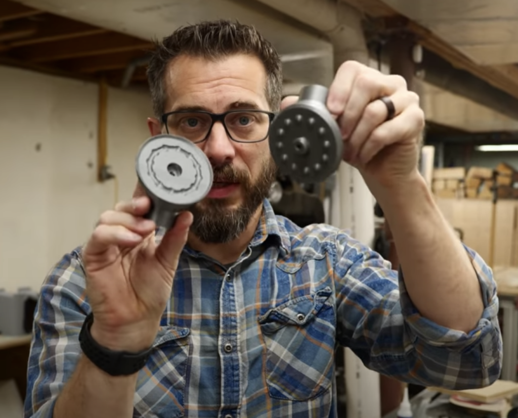
My goal with this project is to create an adjustable work light arm that requires only one point of tension while providing multiple points of articulation. To accomplish this, Josh and I drew out a lot of crude ideas on a marker board. We settled on the idea of a rotating, shoulder-style joint that could rotate along mating faces, but had indexing detents that would prevent slippage once pulled under tension.
Josh designed a two-part joint in Fusion 360 that would fit snuggly into the ends of some left-over clothing rod. I printed the parts on our 3d printer and tested them by running a brake cable from a bicycle through the centers of the two parts. While, yes, the concept worked, the parts had way too much friction. Josh discovered that you could simply rub on some lip balm (later I used paste wax) on the mating surfaces and it provided just the right amount of slip to work really well.
2. Create a Sliding Gantry
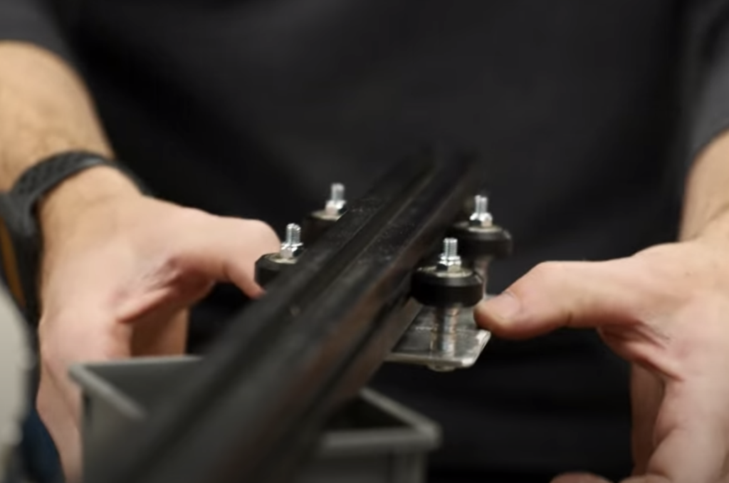
Now that I have the joints mated to the arms, I had to figure out how I could the work light arm to move from the mill over to the lathe. I decided to use some left-over aluminum extrusion that I could mount to the ceiling, parallel to the front of both machines. Just like a CNC or 3d printer, I had to create a sliding platform that uses V-wheels to ride inside the extrusion’s side grooves.
I cut a slide platform out of thin, scrap aluminum and cut some acrylic spacers on my laser cutter. These spacers would allow the wheels to be bolted to the platform while giving enough of a stand-off to move freely. You could use a stack of washers to achieve the same affect. I drilled a hole in the center of the platform and bolted the highest, 3d printed light arm joint to it. This joint wasn’t tightened all the way so it could rotate with a little friction.
3. Add Tensioning System
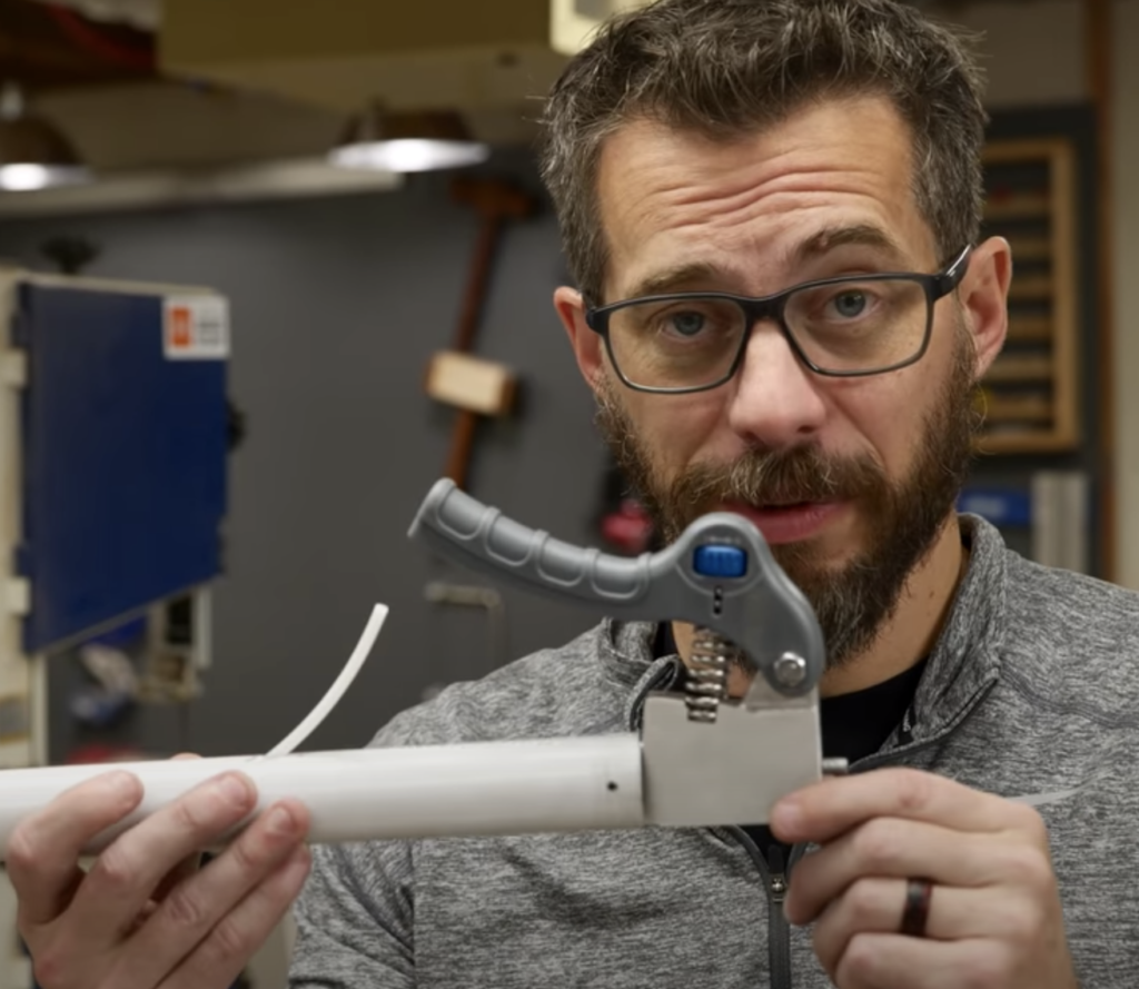
Like I previously mentioned, I’ll be using some bicycle brake cable as the main tensioning medium. The real trick is that the light arm needs to be under constant tension when left alone and free of tension with the single-handed operation. Anthony mentioned that those exercise springs that you squeeze for grip strengthening would work perfectly. After a quick trip to the store, I cut off on part of that grip device and bolted it to a holder that I eventually made out of 1/2″ aluminum.
I attached this tensioning handle to the bottom of the work light arm and drilled some access holes for the brake cable. To prevent the cable from chaffing on the metal holes, I used some PTFE tubing for 3d printing filament to help the cable move through its rang of motion with ease. On the opposite end of the work light arm, I added a clamping bolt to pinch the brake cable and prevent it from slipping. To do this, I drilled a hole in a bolt and passed the cable through that hole. I then tightened on a nut, pinching the cable in place.
This system worked super well! After adjusting the 3d model of the joints to add a collar to help tighten the joints, and I had to tighten the cable significantly (probably still not enough) for the system to hold like I wanted. I was really happy with the range of motion and degree of freedom this design allowed. I could easily slide the light from one machine to the other, spin the arm and fold it around to get the end right where I wanted it.
4. Install the Light
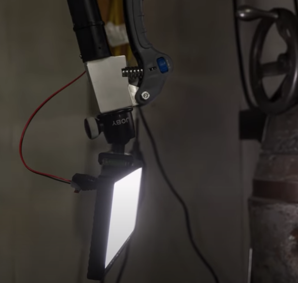
Now that the light arm was completed and working great, I had to add the actual light. Anthony found a small, but intensely bright LED panel online that would work perfectly. Lights like these are marketed toward photographers so they have a lot of the same hardware attachment points. One super common mounting point is a 1/4-20 bolt thread. You’ll see this in most camera bases, tripods, and quick attachments. I had an old uni-ball head from Joby that allows the attached item to swivel around on a ball. He mounted the Joby head onto the light panel and we attached it to the tensioning handle mount.
I ran some additional 2-conductor wire from the back of the light, up the work light arm, and down to a plug so that the light could remain on instead of battery powered. While the work light arm was a single-hand operation, the light has a knob to adjust its position. I really like this design and it illuminated my work area wherever I want. The whole mechanism is really cool, and with another round of refinement can rival any camera or light booms available.
Tools List:
(purchasing via these affiliate links supports ILTMS)
Woodworking:
- Dewalt 20v drill driver combo
- Jet Wood Lathe 12×21
- Carbide lathe tool set
- Countersink drill bits
- Dremel tool
- Grizzly Drill Press (WAAAAY overpriced (3x) on Amazon, buy from Grizzly directly.)
- Shop Fox Hanging Air Filter
- 2HP Dust Collector
- 1 Micron bag
- Speed square
- 11″ Digital protractor
- Digital Angle Gauge
3d Printing/CNC/Laser:
Welding:
Electronics:
- Multimeter
- Wire
- jumpers (Male to Female)
- Soldering iron
- Third hand kit
- Wire strippers (not the ones I have, but good ones)
- Thin solder
- Anti static mat
- Fiskars cutting mat
- Plastic parts cabinet (24 drawer)
- Plastic parts cabinet (64 drawer)
- Precision Screw driver kit
Other Stuff: