
I recently cleaned up my desk and was pretty proud of how minimal it looked. There wasn’t much sitting around to distract me anymore, but I quickly realized I had a problem – I didn’t have a place to charge my phone. I could have bought a nice charger to sit on the desk, but that would defeat the purpose of keeping things clean and minimal. I thought about embedding an inductive charger into the desk itself, but another idea caught my attention.

Initially, I considered creating a charging tray that would slide out from under the desk. Then I thought it might be cooler if it came out from underneath the monitor. That’s when I remembered some people use their iPhones as continuity cameras, and everything clicked into place. I wanted to design a mount that would attach to the back of my monitor with a magnetic charger. The phone could sit in a position where I could see the screen, or if I needed to use the camera, it would fold up so the camera faced outward while still staying on the magnetic charger.

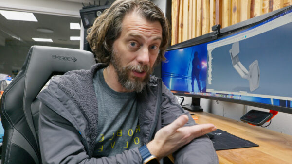
The challenge was figuring out how all the joints would work. I needed to create a system where these joints would stay in place with the phone in different positions without having to constantly tighten and loosen things. I started with an inexpensive MagSafe charger from Amazon that works with my iPhone. These chargers use magnets built into the phone to hold it securely while charging, yet allow for easy removal. The first step was taking measurements with calipers and building a model of the disc in Autodesk Fusion so I had something to build around. If you’re interested in learning Fusion, our online course Fusion for Makers is an excellent resource that I’m currently updating for 2025 with all the latest features.
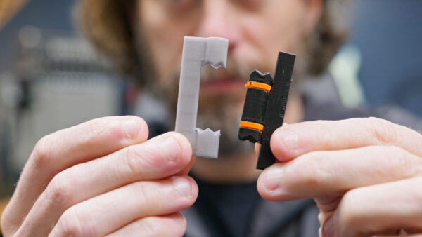
After figuring out how to model the disc, I shifted focus to the hinges, which turned out to be the most interesting part of the project. I needed to create hinges that were tight enough to hold multiple pieces in various positions but loose enough that I could easily move them where I wanted. I had tried springs and cables in the past, but this time I wanted to see if I could do it with just 3D printing. My idea was to use flexible material like TPU to build compressible spacers between the rotating pieces, creating a sort of locking mechanism with teeth that would hold position.
Modeling this proved challenging. I needed to create pieces that looked like a pie crust with wavy lines coming out from the center of a circle. After spending a long time figuring it out, I discovered the loft tool in Fusion was the key. I created a flat sketch and another sketch for the outside point, then lofted between them. This seemingly simple shape took me surprisingly long to model correctly, but once I had it, I could create the locking mechanism I needed for the hinges.
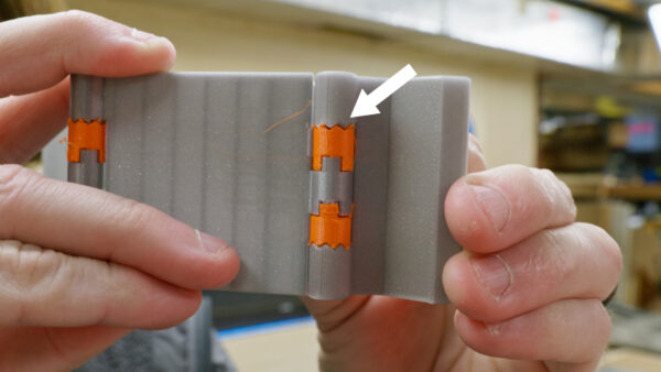
I went through several test prints, trying different approaches. First, I printed static pieces in different colors to see what was happening – orange for the flexible material and gray for the rigid parts. My initial thought was that small flexible pieces would allow the outer pieces to compress and fit together, but this led to breakage. I then tried making the entire end of each hinge part flexible, which worked much better. I also made the outside of the hinge solid to prevent breaking. With these adjustments, the hinge worked well, snapping between positions and staying in place.
The design needed at least four main components: a mount for the back of the monitor, an arm to hold everything, a third piece to reach over or under the monitor, and a fourth piece to hold the phone that could flip up or down. I printed all these parts separately rather than together, which gave me better quality and faster printing times. I had to print several versions of the flexible pieces to get the right fit, but eventually found the perfect size where they snapped into place between positions. I also added stainless steel pins to hold everything together and prevent the pieces from pulling apart when twisting.
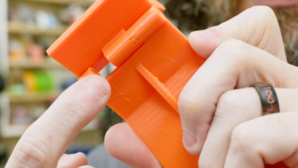
Well, I soon realized a problem – while the joints held in place when unloaded, once weight was added to the end, the arm would droop due to the slop in each joint. The problem was that there needed to be enough space for the teeth to move past each other, but this space created leverage problems with the weight of the phone. I could make more and smaller teeth to reduce the slop, but that would require reprinting everything. After getting deep into this design, I realized I had hit a dead end – the compound effect of the weight and slop in multiple joints meant the arm simply wouldn’t hold its position reliably.
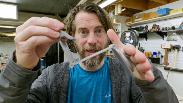
Instead of giving up completely, I tried one more hinge design. Rather than relying on friction between surfaces, I used a castle nut approach where pieces engage and lock together, held in place by spring tension. You can compress the spring to separate them, change their position, and then the spring pushes them back together. This worked beautifully – just push the pieces apart, turn them, and they seat themselves back together and lock in place. The final mount attaches to the back of the monitor with strong double-sided tape, and you can easily move it out of the way by sliding it slightly and swinging it up.
This project ended up being less about creating a phone dock and more about problem-solving and persistence. I was close to abandoning the whole thing and calling it a failure, but trying one more approach led to success. Even if the solution isn’t perfect, it opened a new path to follow. If there’s anything to take away from this experience, it’s not to give up too quickly. Sometimes you just need to try something different to find the solution that works. That’s what making is all about – learning through repeated attempts and adapting when things don’t go as planned. Thanks for being here, now go make something awesome!
TOOLS
(purchasing via these affiliate links supports ILTMS)
Woodworking
- SawStop cabinet saw
- 8″ Dado stack
- Skil circular saw
- Dewalt 20v drill driver combo
- Dewalt Miter Saw
- Jet Wood Lathe 12×21
- Carbide lathe tool set
- Countersink drill bits
- Dewalt DW735 benchtop planer
- Orbital Sander
- Pancake compressor/nail gun combo
- Dremel tool
- Incra box joint jig
- 54″ Drywall T-Square
- Push Blocks
- Jigsaw
- Shop Fox 6″ Jointer
- Grizzly 14″ Bandsaw
- Grizzly Drill Press (WAAAAY overpriced (3x) on Amazon, buy from Grizzly directly.)
- Jet Drum Sander
- Kreg Rip Cut (circular saw guide)
- Kreg R3 pocket hole jig kit
- Shop Fox Hanging Air Filter
- 2HP Dust Collector
- 1 Micron bag
- Speed square
- 11″ Digital protractor
- Digital Angle Gauge
- Classic steel ruler (cork backed)
- Taper jig
- Flush cut saw
- 90˚ corner clamp (4 pack)
- Box Cutters (for eva foam)
3d Printing/CNC/Laser
- Glowforge (laser)
- X-Carve (CNC)
- Ultimaker 2 Extended 3D printer
- Ultimaker 3
- Original Prusa i3 MK 3
- Form1+ SLA 3D printer
- Silhouette Portrait (vinyl cutter)
- All filaments, 3d printing supplies from MatterHackers